
Enclosure design guide
How to Design a Plastic Enclosure for Electronics
A practical guide to enclosure design for electronics, written for the engineer who will draw the housing. It follows the rules our own team designs to for the CNC-machined, thermally bent sheet process, so the model you send comes back as a prototype rather than a list of questions.
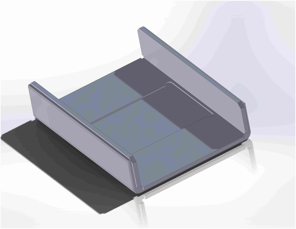
Start here
How to design a plastic enclosure that will be cut, bent and bonded.
How to design a plastic enclosure depends on how it will be made. A molded enclosure is designed as a cavity. A Toolless enclosure is designed as a set of flat patterns: sheets that are CNC machined, scored on a V-groove saw, folded on a thermal bender and solvent bonded into a rigid body. Thinking in flat patterns from the first sketch makes every feature a question of which face it lives on and whether that face is bent or bonded.
You do not have to model the joint details. Send the enclosure as a solid with the walls, openings and hardware you need, and our engineers add the tongue-and-groove, the bend allowances and the flashing during the review that precedes every prototype. The full rule set lives on the designs and details and functional features pages; what follows is the order in which to apply it.
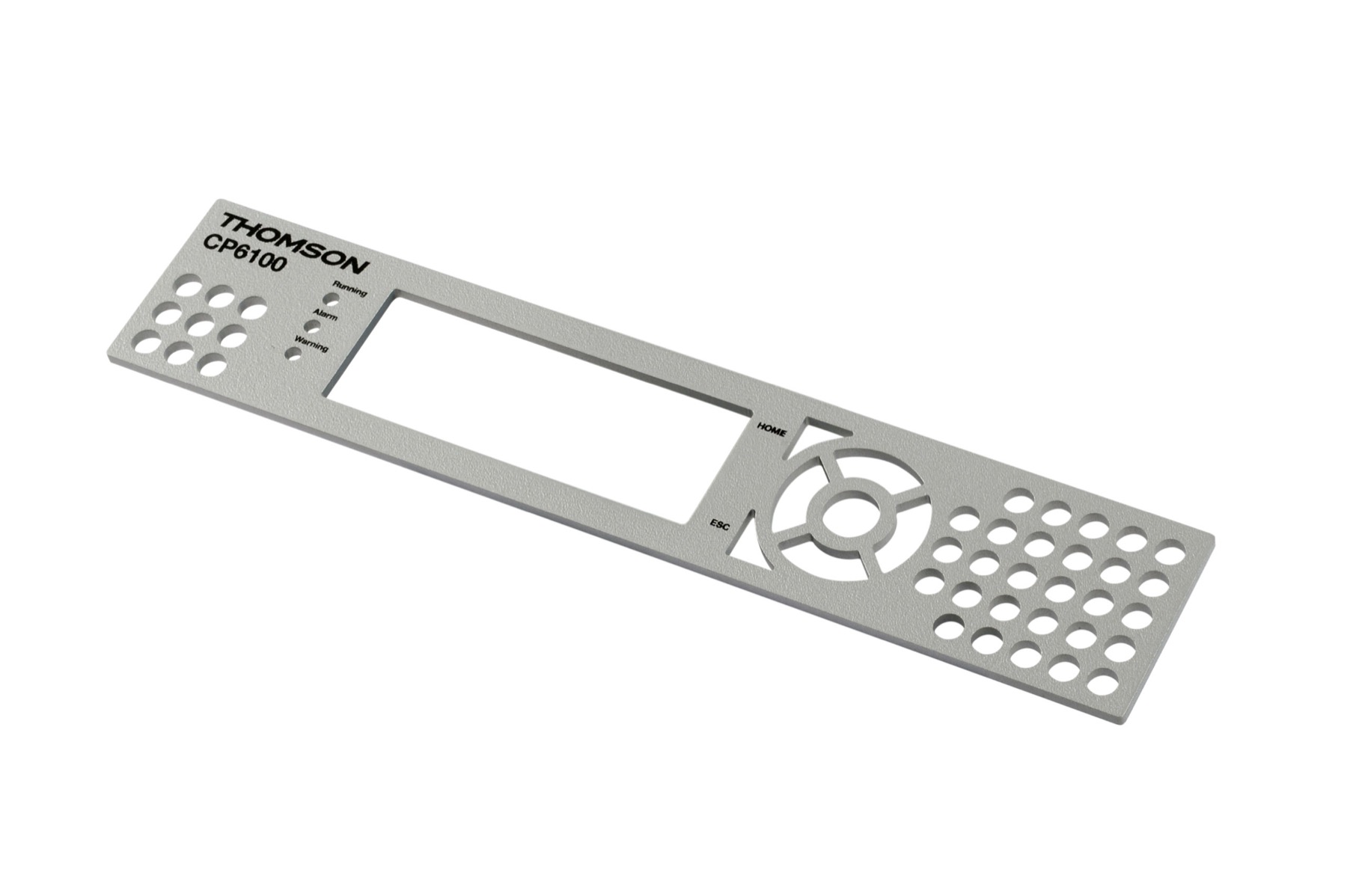
The design sequence
Eight steps from board to enclosure model.
Fix the contents
Model the PCB, display, connectors, battery and cable bends at their real size. Leave service clearance around anything a user or technician will touch, and note which connectors face which way.
Pick material and gauge
General-purpose ABS in 3, 4, 6 or 8 mm covers most housings. Choose flame-retardant ABS or Boltaron for UL94 V-0, polycarbonate for impact and clarity.
Split the body into flat patterns
Decide which faces fold from one sheet and which are separate bonded pieces. An average enclosure is eight pieces in two thicknesses. Fewer pieces and more bends means less machining and less bonding.
Place the bends
Dimension to the inside walls; the outside grows by one thickness per bend. Standard bends go up to 115 degrees and 40 inches long, reverse bends to 45 degrees. Curves are rolled in one direction only.
Position the joint lines
Joints cannot be hidden, so place them where they read as a feature and where a wipe-down reaches them. A 0.5 mm chamfer on the tongue edge turns each seam into a deliberate cosmetic line.
Add bosses and inserts
Self-tap bosses for screws installed once or twice, 4 mm minimum thread depth. Brass inserts for repeated service. Keep bosses under 9 mm tall and combine them where you can; taller supports become sidewall tabs or frames.
Cut the openings
Keep machining on one side of each sheet; reverse-side features double the labor. Vents as slots at 2 mm minimum width, pockets over about 9 square inches as through-cuts with a bonded insert, windows recessed from the rear.
Send it for review
Export STEP, IGES, SAT, SolidWorks, STL or DXF and upload it. An engineer checks the model against every rule, adds the joint details and returns a 3D model for approval before cutting.
Wall thickness and bends
The numbers behind the sheet.
Wall thickness in a sheet enclosure is the sheet gauge, chosen per piece rather than per feature. The table below is the set of dimensions our benders and routers hold, taken from the shop's own design rules.
- Stock gauges
- 3, 4, 6 and 8 mm ABS; 2 mm to about 12 mm across all materials
- Machining tolerance
- ±0.2 mm on the flat pattern; ±0.4 mm reverse to front
- Maximum bend
- 115 degrees up, 45 degrees reverse, 40 inches long
- Bend radius
- Square inside on a 90 degree bend; outside radius one material thickness
- Edge radii
- 1, 2 and 3 mm standard; keep a flat land for the router bearing
- Joint clearance
- Net fit at extreme tolerance, nominal 0.2 mm
- Boss height
- Under 9 mm; self-tap thread depth 4 mm minimum
- Vent slots
- 2 mm minimum width, cross supports retained
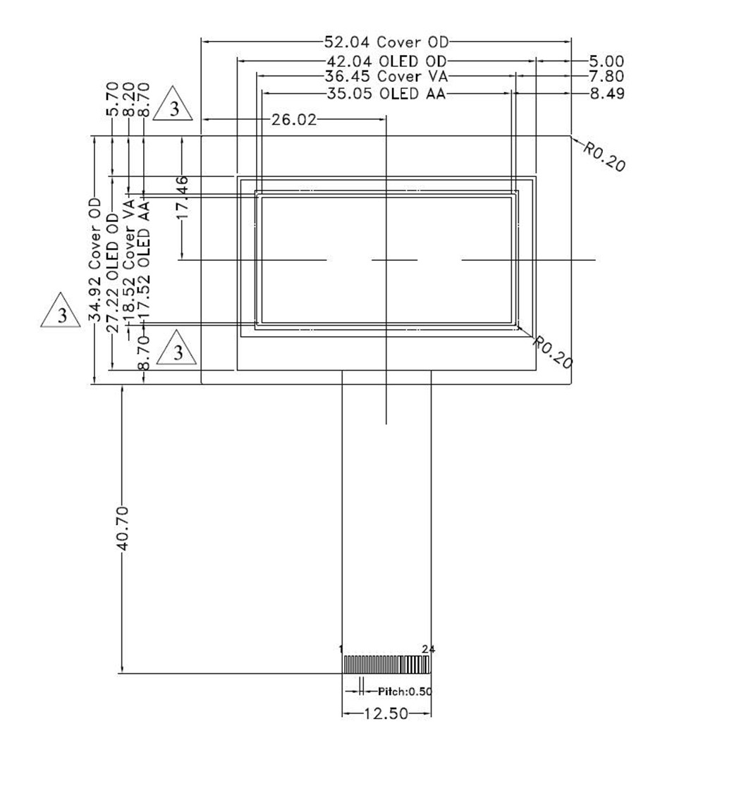
Design rules
Electronic device enclosure design, checked line by line.
Our engineers look for these first. A model that satisfies them moves straight to quoting; one that does not comes back marked up with the fix for each.
- Every piece is a flat pattern machined on one side
- Dimensions are taken to the inside walls
- No bend runs in two directions on the same sheet, and no groove stops short of a panel edge
- Bends of less than 90 degrees are closed with caps or end plates, because the bending cut shows
- Joint lines fall where they look intentional and can be cleaned
- No solvent joint is loaded in tension
- Bosses are combined, under 9 mm, and brass-inserted where a screw cycles
- Slide-in doors have a frame or an undercut; other doors use a fastener and insert
- Acrylic windows bond from the rear; polycarbonate windows mount behind a bezel
- Fan inlet area matches outlet area, and the vent pattern stays as open as the wall allows
Finish and hardware
Decide the decoration before the flat pattern is final.
Printing, engraving and hardware all affect where openings and recesses go, so they belong in the model rather than in a later note. Full-color digital printing goes straight onto the sheet with white ink and raised TEXTUR3D options; it adheres better than silk screen and needs no recess.
Standard hinges, latches, belt clips, DIN clips and key locks cost less than custom features and are easier to service; solvent-bonded acrylic hinges need no fasteners at all. See the catalog of enclosure types and components.
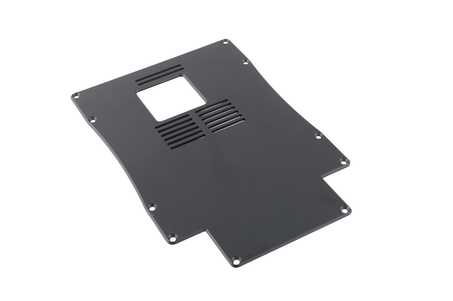
Related
The rule pages behind this guide.
Designs and details
Machining, edge, bending and assembly rules with every dimension.
ReadFunctional features
Bosses, inserts, doors, vents, windows, decoration and hardware.
ReadTechnology matrix
Toolless against injection molding and pressure forming, line by line.
ReadToolless vs 3D printing
Where a bent-sheet enclosure beats a printed one for a real product.
ReadQuestions
Enclosure design questions, answered.
Do I need to model the tongue-and-groove joints and bend allowances?
No. Model the enclosure as a solid with the walls, openings and hardware you need, and leave the joint details out. Toolless adds the tongues, grooves, chamfers and flashing during the engineering review, then returns a 3D model for approval before cutting.
Can you bend all four sides of a panel up like sheet metal?
No. The V-groove is cut on a table saw and runs the full width of the panel, and the thermal bender has no interchangeable fingers. A box is designed as bent sections plus bonded end pieces. Curves are possible, formed in one direction.
What if I do not have CAD at all?
Send the board, the connector list and a sketch or a description of the mounting and environment. Our engineers design the enclosure in SolidWorks, one engineer manages the job, and the design belongs to you once the prototype is purchased.
How strong is a bent and bonded enclosure?
As strong as an injection-molded part from a similar material. It withstands the usual drop tests, and where a specific mechanical test applies we add thicker material, corner doublers, ribs and reinforcement at the glue joints.
Why engineers choose Toolless
Trusted for enclosures since 1998.
Startups, OEMs and medical device makers across the USA, Canada and Australia come back for the next run. Read more testimonials.
- Years without molds
- 25+
- Certified quality system
- ISO 9001
- Units per order
- 1–10,000
- Sq ft in Everett, WA
- 13,000
“We initially considered injection molding, but with our volume the cost of tooling would never be recovered. It took only a week to settle on a design and get a prototype, and we were in production a week later.”
“I spent 9 years as a quality engineer at Rockwell and tend to be a perfectionist. Your professionalism and diligence in helping evolve our cover is greatly appreciated.”
“After a number of orders, Toolless have become our preferred supplier. Even though we are located in Australia, all deliveries have been fast and hassle free.”
Start your enclosure
Send the board. We’ll send the box.
Quotes come from an engineer, not a form robot. Attach CAD, photos or a sketch and we reply within one business day.