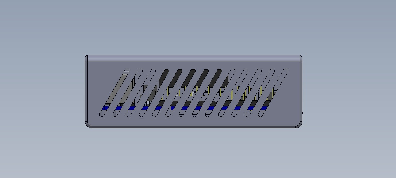
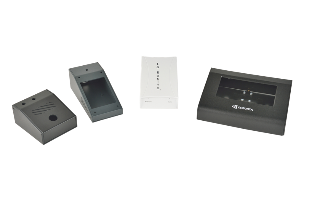
A product built on a Raspberry Pi usually outlives the board it launched with. Between the Pi 3B+, the Pi 4 and the Pi 5 the mounting holes stayed put while the connectors moved; HATs are redesigned; some teams move to a Compute Module on their own carrier board. This post is about designing a custom Raspberry Pi enclosure so that each of those changes is an edit to a CNC program, not a new case.
With a mold, a moved connector means reworking the tool, so the case tends to freeze the board choice. A sheet-fabricated case has no tool to rework, but design still decides how much a board change touches: one window, one panel, or the whole enclosure.
What stays the same between Pi models, and what moves
Every full-size Pi since the Model B+ shares an 85 × 56 mm outline and four M2.5 mounting holes on a 58 × 49 mm rectangle. Almost everything else has moved at least once.
| Feature | Pi 3B+ | Pi 4B | Pi 5 |
|---|---|---|---|
| Mounting holes | 58 × 49 mm, M2.5 | Same | Same |
| Display output | One full-size HDMI | Two micro HDMI | Two micro HDMI |
| Power input | Micro USB | USB-C | USB-C |
| USB and Ethernet end | Reference layout | Ethernet and USB swapped | Swapped again relative to the Pi 4 |
| 3.5 mm audio jack | Yes | Yes | No |
| Power button and fan connector | No | No | Yes |
A case cut tightly around one model will not take the next. The parts that depend only on the hole pattern will, so the aim is to make as much of the case as possible depend on nothing else.
Put the datum on the mounting holes
Set the case’s coordinate system on the mounting-hole pattern, not on a board edge or a case wall. The bosses sit at the holes, and every cutout is dimensioned from them. The holes are what the board is actually fastened to, and they are the one feature that has not moved since the B+.
With that datum, a board change moves cutouts and nothing else. In our process the bosses are bonded into recesses machined from the same program, with M2.5 brass inserts heat-staked into them, so the base, the bosses and the fasteners stay identical across board revisions. The revision is confined to the openings.
Give the height the same treatment. Leave a few millimeters above today’s tallest component, because the next board or HAT may need a taller heatsink or a fan, and a Pi 5 under sustained load usually wants active cooling and a clear air path. Spare headroom costs a few millimeters of sheet; adding it later means a new lid for every unit already in the field.
Tight windows or generous windows
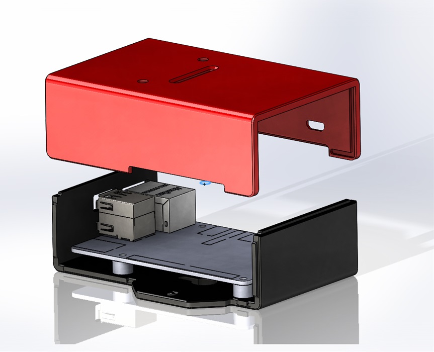
A tight window, one per connector with a small clearance around the plug, looks finished, guides the plug in and keeps dust and fingers out. It also locks the case to one connector layout. A generous window spans a whole connector zone, for example one opening across the USB and Ethernet end. It accepts more than one board layout at that end but looks less finished and leaves more of the board exposed.
In a no-tooling process, moving a tight window is a program edit either way, so the real reason to design generous openings is the cases already built: units in the field that may receive a replacement board, and cases on your shelf when a board supply changes. If neither applies, keep the windows tight and revise them when the board changes.
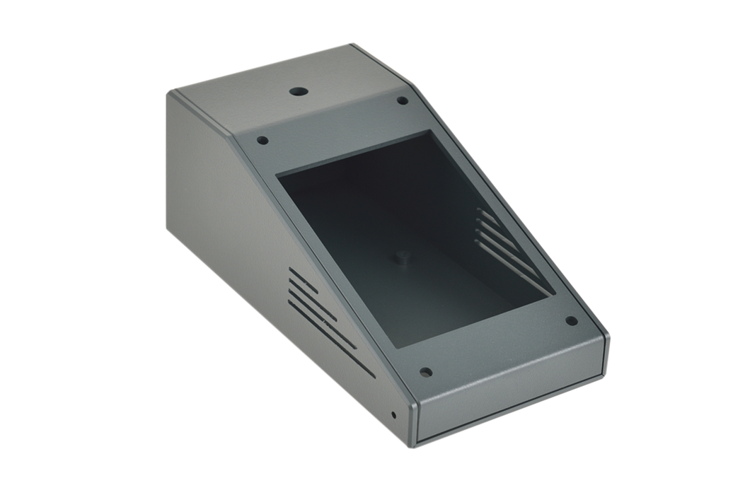
A middle path is a punch-out: an opening for a future connector that stays closed until that connector is fitted. One of our Pi 4 cases, pictured below, carries punch-out options for future connectors.
Put the connector face on its own panel
Where the connector layout is the part most likely to change, put it on a separate flat piece. Our U Box construction does this by default: a U-shaped body, a matching cover and two end panels. A board change reprograms one end panel, while the body, cover, printing and inserts stay as they are. The same body can also run with two end-panel variants at once, for example one product shipped on Pi 4 and Pi 5 boards during a transition.
In a two-piece C Box the ports are cut into the bent halves, so a board change touches a bent part. It is still a program edit, but each variant is a complete half rather than a small panel. If field units must accept a new board, make the connector panel removable, held by screws into brass inserts, so a technician can swap the board and the panel together.
Compute Module carriers move the problem to your PCB
With a Compute Module, the connectors are on your own carrier board, and their positions are your decision. That is the strongest protection a case can have: keep the carrier outline, mounting holes and connector positions fixed across carrier revisions, and the enclosure does not change when the electronics do.
Two habits make that work. Freeze the carrier’s outline and connector placement early and treat a connector move as a change that needs the case engineer’s sign-off. And put the connectors on one or two edges, so that if one must move, only one panel follows it.
Revision control for the case
Give the case its own part number and revision letter, and record which board and HAT revision each case revision fits: case rev A for the Pi 4 with HAT v1, rev B for the Pi 5 with HAT v2. The case drawing should name the board revision it was checked against.
Because the case is a program rather than a tool, an older revision can be cut again for spares while production runs the newer one, and a change between blanket order releases rides along on the next release. Prototype every board change before the release; a revised case takes 3 to 21 working days, so start it as soon as the new board is chosen. Our page on design changes without a mold compares each kind of change with mold rework.
Planning a move to a newer Pi or a Compute Module carrier? Upload the current case model and the new board on our CAD upload page, and we will mark up what has to change.